[racket] machine states diagrams
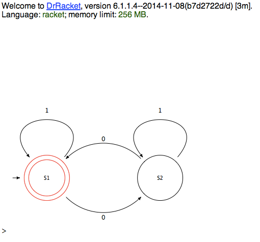
Here is an example drawing a simple state machine with MetaPict.
It shows a little state machine that accepts numbers with
an even number of zeros in its binary representation.

#lang racket
(require metapict metapict/structs)

; Two states S1 and S2.

; Four arrows (here A1, A2, A3, A4)
; A1:  S1 -- 0 --> S2
; A2:  S2 -- 0 --> S1
; A3:  S1 -- 1 --> S1
; A4:  S2 -- 1 --> S2

; S1 is the start state.


;;; Drawing

; S1 has center P1
; S2 has center P2

(define P1 (pt 0 0))
(define P2 (pt 5 0))

; Circles has radius 1.

(set-curve-pict-size 400 400)
(with-window (window -2 7 -2 7) ; xmin=-2, xmax=2, ymin=-2, ymax=5
  ; The states S1 and S2 are drawn as rings (circles).
  (define R1 (circle P1 1))  ; center P1 radius 1
  (define R2 (circle P2 1))
  ; Since S1 is an accepting state it gets an extra, smaller ring.
  (define R3 (circle P1 0.8))

  ; We make circle shapes nodes for S1 and S2 with a
  ; slighter larger radius. The nodes are used to place the arrows.
  ; The image becomes prettier, if the arrows don't touch the states.

  ; Nodes for S1 and S2. Nodes have attachment points for the arrows.
  (define N1 (circle-node P1 1.2)) ; center P1, radius 1
  (define N2 (circle-node P2 1.2)) ; center P1, radius 1
  ; The start node S1 gets an extra inner circle.
  (define S1-inner (scaled 0.8 unitcircle))

  (define A1 (draw-edge N1 N2         ; arrow from S1 to S2
                        (vec  1 -1)   ; leaving S1 in direction south-east
                        (vec -1 -1))) ; direction from S2 center to
attachment point
  ; Note: The attachment points are calculated base on the shape of node.
  (define A2 (draw-edge N2 N1 (vec -1 1) (vec  1  1)))
  ; The direction (vec 1 1) has angle of 45 degrees with the x-axis.
  ; Directions can also be specified with (dir d) where d is in degrees.
  ; Here the degrees are chosen such that the arrows don't touch each other.
  (define A3 (draw-edge N1 N1 (dir 50) (dir 130)))
  (define A4 (draw-edge N2 N2 (dir 50) (dir 130)))

  ; The states S1 and S2 have labels centered (cnt):
  (define LS1 (label-cnt "S1" P1))
  (define LS2 (label-cnt "S2" P2))

  ; Let's call the the midpoint between S1 and S2 for M.
  (define M (med 1/2 P1 P2)) ; M is 1/2 of the way from P1 to P2.
  ; The arrows have labels.
  (define L1 (label (text "0") (pt- M  (vec 0 1.5)) (bot))) ; bot =
bottom i.e. below point
  (define L2 (label (text "0") (pt+ M  (vec 0 1.5)) (top))) ; top =
top i.e. above point
  (define L3 (label (text "1") (pt+ P1 (vec 0 3))   (cnt))) ; cnt =
center i.e. on top of point
  (define L4 (label (text "1") (pt+ P2 (vec 0 3))   (cnt)))

  ; Finally a little arrow to indicate that S1 is the starting state
  (define A5 (draw-arrow (curve (pt -1.5 0) -- (pt -1.2 0))))

  ; Draw the two states.
  (draw
   ; rings for state S1 are red:
   (color "red" (draw R1 R3))
   ; use default color (black) for the rest:
   R2             ; ring from state S2
   A1 A2 A3 A4 A5 ; arrows
   LS1 LS2        ; state labels
   L1 L2 L3 L4    ; arrow labels
   ))


The resulting diagram is attached.


--
Jens Axel Søgaard


2014-12-02 11:35 GMT+01:00 Catonano <catonano at gmail.com>:
> Someone suggested me that a module for Racket exists that can produce some
> very nice diagrams of scheme machine states.
>
> Would anyone point me to that ?
>
> I'm in this SICP study group and I'd love to provide some sensory proofs of
> the internal workings of the machine.
>
> Thanks
>
> ____________________
>   Racket Users list:
>   http://lists.racket-lang.org/users
>


--
--
Jens Axel Søgaard
-------------- next part --------------
A non-text attachment was scrubbed...
Name: state-machine.png
Type: image/png
Size: 40173 bytes
Desc: not available
URL: <http://lists.racket-lang.org/users/archive/attachments/20141202/26ee14fc/attachment-0001.png>